
Techniques > Sites > Coronation Offshore (1691)
Site: Re-Surveying the Coronation Offshore Site (1691)
Techniques: 3D Trilateration, Acoustic positioning


|
The Coronation was a 2nd rate Royal Navy 96 gun warship built in 1685, she sank 1691 whilst attempting to get into the shelter of Plymouth Sound in a hurricane. The shipwreck site is sepatated into two areas off Penlee Point on the west side of the Sound, the shallow Inshore site and the deeper Offshore site.
In 1996 the Plymouth Maritime Archaeological Interest Group (PMARIG) started to use the Offshore Coronation site for experiments into underwater surveying and recording methods. This shipwreck was ideal as a test site as it had many guns and anchors to be positioned (Fig. 1), being large in size (60m x 35m) and having big changes in depth it was also difficult to survey accurately.
The site had already been mapped by Peter McBride in 1977 so a detailed and accurate plan could be used as a starting point for the new survey work. The re-survey in 1996 was to be done using 3D trilateration with processing using the recently developed Site Surveyor program, the predecessor to Site Recorder. The work on the offshore site by PMARIG stopped in 1999 once it had been completed but other work on the site has been continued my many different teams since then.
All figures except 1 are taken from the Site Recorder file for the Coronation wreck.
Click on any image below to show a larger version.
Installing Survey Control
A survey control point network was installed on the Coronation Offshore site using the 1977 site plan as a reference (Fig. 2), ten control points were placed on the reef so that they surrounded all the known features. The site is 35m wide so it was not possible to accurately measure from one side of the site to the other while still keeping all tape measurements below the 20m length limit. So two additional points were installed in the centre of the site (CP9 & 11) to allow measurements to be made across the site in two stages. The positions of these points was also determined by the shape of the seabed so the points had to be put on the top of the reef so distance measurements could be made between them. The completed network design can be seen in figure 3 with sets of distance measurements forming braced quads between the control points. More about network design...
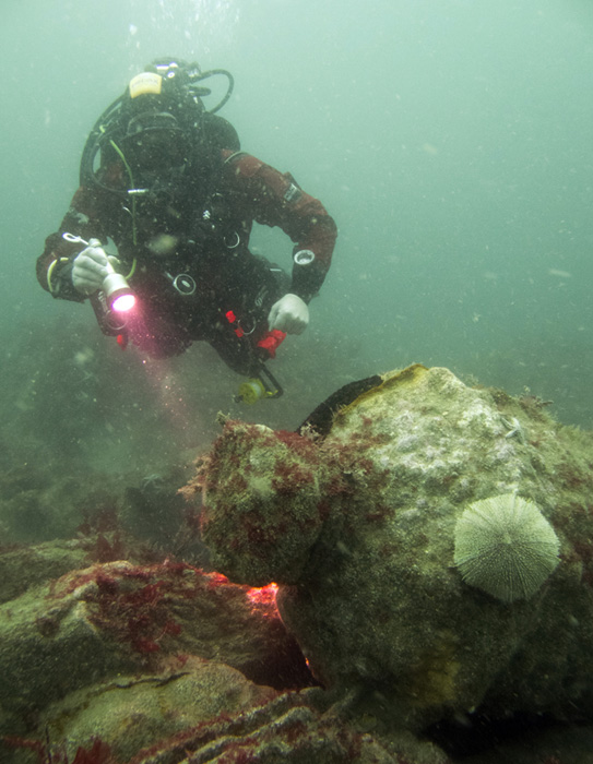
Fig 1: One of the large cannons lying on top of the reef on the Offshore site
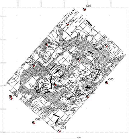
Fig 2: The original McBride site plan overlaid with the planned positions of the control points
The control points installed on this site were large galvanised coach bolts hammered and cemented into crevices in the rock. The seabed in this area is rock reef with pinnacles extending up 3m from gullys filled with sand and gravel. Each control point had a label attached and was marked with a small float to make it more visible. More about survey points...
Once the points were in place the distance measurements were made between the points as shown in the plan (Fig. 3) with depth measurements made at each point using a digital dive computer. The distance and depth measurements were processed in Site Surveyor and the all fitted together to within 12mm (RMS). The control points were then fixed within the software so they could be used for the next stage.
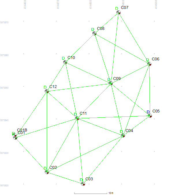
Fig 3: Distance and depth measurements (green) made between the control points
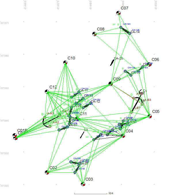
Fig 4: Distance measurements made from the control points to detail points on the guns and anchors
The next step was to position the guns and anchors within the control point network. Two points were positioned on each gun to get both a position and an orientation, with one on the highest point on the base ring and the other on the highest point on the muzzle. Three detail points were positioned on each anchor, one on the top of the shank and one each on the ends of the two flukes. Each detail point was positioned using four distance measurements to the nearest control points ensuring measurements were made from all round each detail point. A depth measurement was made at each detail point and was added to the processing. The positions of the detail points was calculated in Site Surveyor with all points positioned to within 15mm.
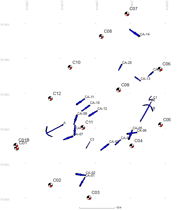
Fig 7: Drawings of the guns and anchors positioned on the site
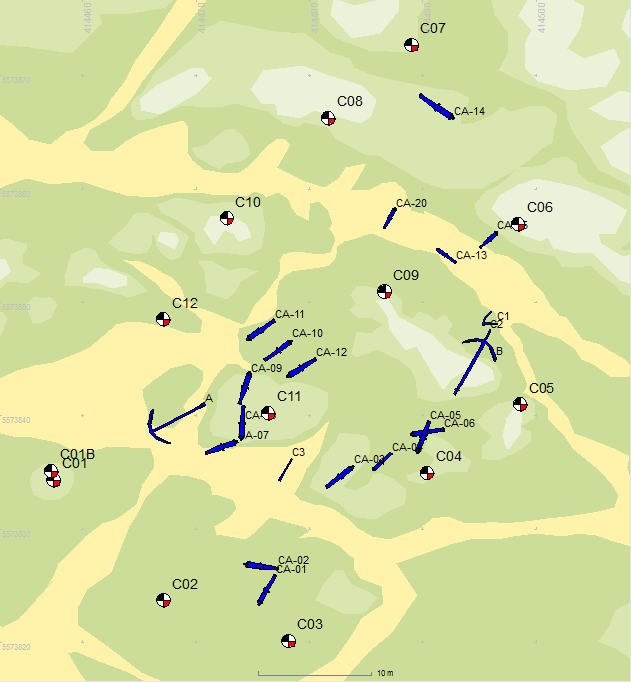
Fig 8: Guns and anchors shown over a chart showing the bathymetry and seabed type
The site plan was later imported into Site Recorder, the guns and anchors were drawn and added to the plan (Fig. 7). The shape of the seabed was recorded along with the seabed type and that too was added to the plan (Fig. 8), low sand gullys are shown in yellow with rocky reef in shades of green.
Real World Positions
As an experiment, acoustic positioning was used to determine the position and oriientation of the site. It is more usual to do this by taking a surface positioon fix with a hand held GPS receiver over a buoy attached by a line to a point on the seabed, see Positioning using GPS. On the Coronation site an acoustic positioning method was used, one used in the oil prospecting industry to compute the position of seismic cables laid on the seabed. Four small Sonardyne acoustic transponder beacons were placed by divers on known points on the site.
An acoustic positioning system was fitted to the survey boat and was used to measure acoustic range (distance) measurements simultaneously to the four beacons. At the same time the positioning system recorded the position of the survey boat from a differential GPS receiver. The survey boat was sailed around the outside of the site collecting acoustic ranges and GPS positions these were passed into a suite of processing software which calculated the best estimate of position and an estimate of position error for each of the marker beacons. Using this method the points on the site were positioned to within 0.3m in 18m water depth, a better precision than could be achieved using the more usual GPS fix on a marker buoy.
Related Pages
Bibliography and Links
- Holt P., 1997, Positioning of the ‘Coronation Offshore Site‘ Off Penlee Point , Plymouth, UK. Survey Report, PMARIG, Ref. S054
- Coronation (1691) on the SHIPS Project web site
- The Coronation Wreck Project