
Sites > Firebrand > Firebrand #2 - Analysis
Site: Surveying the fireship Firebrand (1707)
Survey Accuracy Analysis [Advanced]
Analysis of the results of this survey and recording work may help us identify areas in which the process can be improved. The planning phase for this survey work included the design of an ideal control point network for the site.
Comparisons between the ideal design and the installed design show that what was installed was close to what was planned but was limited in a number of ways. The main limitation in the network design was the shape and substance of the seabed; the rock ridge to the west of the site limited the width of the network as did the boulder slope to the east. This meant that the installed network was three times as long as it was wide (46m x 15m), whereas the ideal for optimum positioning is no more than twice as long as wide. The rocky seabed also caused problems with line of sight between CPs as the points themselves could not easily be installed on the tops of the large, rounded granite boulders that surround the site.
Adjustment of the distance and depth measurements showed that they fitted together (RMS of residuals) in the order of 16 to 30mm, typical for this kind of work. With the given network geometry this produces a post-computed position error estimates of 100mm (95% semi-major) for a typical point inside the network. This means that we have a 95% confidence that the position of any point within the network is within 100mm overall, this looks like a large figure but it is typical for a conventional tape trilateration survey. In practice the limits of precision show up as differences in the positions of objects on the seabed positioned using different methods.
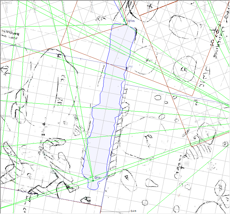
Figure 1 shows the location of Gun 1 on the site plan positioned using both direct distance measurements and a planning frame drawing. The blue shaded drawing is the estimated position of Gun 1 based on a separate drawing of the gun and the two detail points that position it. Underneath is the scanned planning frame drawing of that same part of the seabed also showing the outline of the same gun. For this object the drawn position for the gun matches up very well with the two detail points used to originally position the gun on the site.
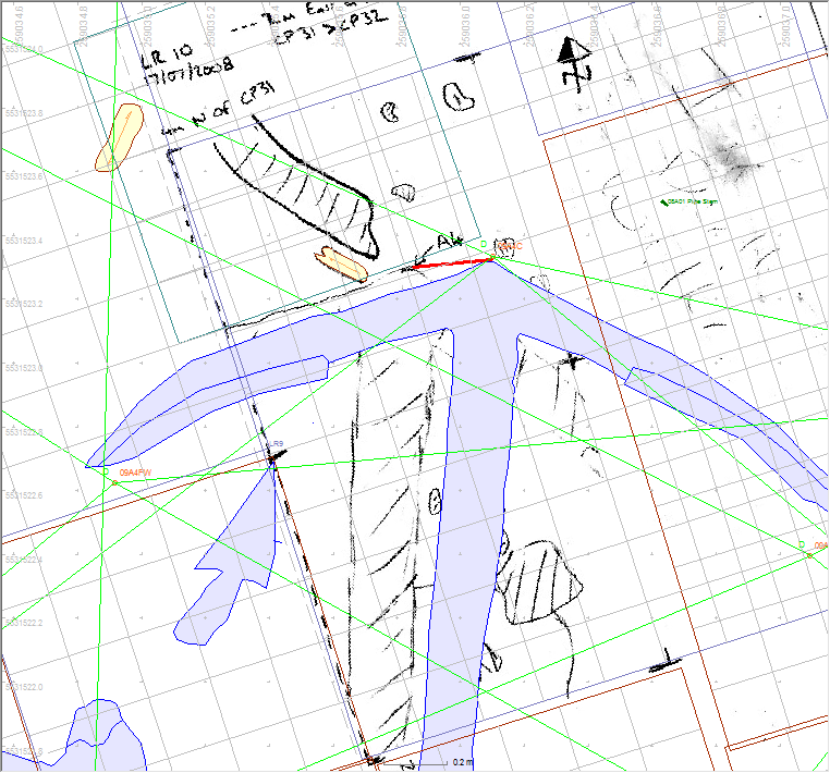
Figure 2 shows a similar comparison for Anchor 4, here the crown of the anchor on the site plan is 215mm to the east of the same point on the planning frame drawing. If we consider how each position is derived we may learn more about the reason for this discrepancy. For this we will only consider relative accuracy as absolute accuracy (in real world coordinates) below the metre level is hard to determine and does not affect the archaeological interpretation.
The detail points on the anchor are positioned using a number of direct distance measurements made to survey control points around the site plus a relative depth measurement at each point. The estimated error in each tape measurement is in the order of 30mm so with an ideal control point network the point should be positioned to similar precision. However, the control point network was not precisely positioned relative to itself so errors in the network shape will show up as an increase in the measurement residuals at each detail point.
The comparative inaccuracy in depth measurements will also affect the quality of the position fix. The relative depth measurements of each point have an estimated measurement error of 0.1m and the measurements are usually only reported by the instrument to 0.1m. So the distance measurements are three times more precise than the depth measurements and so have less effect than the distance measurements where the points at either end of the distance measurement are at significantly different depths, as we have with the control network used on the Firebrand. However, where there are less than four distance measurements to each detail point the imprecise depth measurement may have an effect and that may be to skew the position of the point sideways. The easiest solution to this problem is to ensure that each detail point has four good quality distance measurements made to it from four points surrounding the detail point. The second solution would be to use a more precise way to measure relative depth.
The accuracy of the original drawing of the anchor also has to be considered as any discrepancies in the drawing will be highlighted in this comparison. As will differences in the point measured to at each end of the gun where thick concretion obscured the edges of the gun and many of the details. Careful recording and drawing and clear marking of the detail points on the anchor would help minimise errors here.
Click on any image below to show a larger version.
The planning frame drawing is positioned indirectly from a baseline and secondary control points so many factors affect the position accuracy of the scanned drawing on the site plan. The scanned drawing is positioned within a planning frame so there will be a small error in the registration of the drawing within the frame itself, other tests show that this may be in the order of 30mm. The process of hand drawing what is seen under the frame will also incur errors, particularly where there is a large vertical distance between the frame and the seabed. The frame may be positioned relative to a tape baseline laid out between two secondary control points so lateral movement of a long tape will also create positional errors, as will registration of the frame on the tape. Errors in the position of the secondary points will affect the position of the tape baseline and thus the position of the frame. If the post computed position error for any point on site is 100mm (95%) then position discrepancies of the same order of magnitude are to be expected.

A better method would be to position each planning frame separately with two detail points on the seabed, with each detail point positioned with four distance measurements to the primary control point network. This method reduces the chain of position dependencies and makes for more direct positioning of each frame. However, this process takes considerably longer than using a tape baseline to position the frames so a compromise is required between efficiency and accuracy.