
Techniques > Surveying > Survey Methods > 3D Trilateration > Designing Networks
Techniques: 3D Trilateration - Designing Survey Control Point Networks
Version date: 16 October 2016
- Introduction
- Designing networks
- The 'Everything' network
A survey Control Point (CP) is a point where you make distance measurements from on a site and a 'network' of Control Points is simply the name for all of the CPs and the measurements used to position them.
Designing a network of CPs may look complicated but the design is defined by a set of rules and if you follow the rules you will end up with a good design. The aim is to surround the site with a ring of CPs while keeping the distance between any point and its nearest neighbour to less than 20m. Other Secondary points can be added inside the site where the site is more than 20m wide. The CPs around the site should be placed far enough away from the features on the site that they will not be in the way of any excavation work.
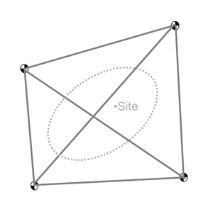
Fig 1: The Braced Quadrilateral
The rules for designing control point networks are below:
- Place a ring of primary control points around the outside of the site
- Use as few points as possible for the CP network
- Networks should be circular or elliptical not pointed
- Make distance measurements from each CP to at least four other points
- Distance measurements between CPs should be less than 20m, preferably less than 15m
- A set of six measurements between CPs should form a braced quadrilateral, see below
- Mount CPs high up so they have a clear line of sight to other CPs
The Braced Quadrilateral
If you take four CPs and measure the six distances between them the shape of the network is called a braced quadrilateral, or braced quad (Fig. 1). The measurements around the outside of the four points form a quadrilateral and the two inside measurements are braces. This is a special shape for surveying using distance measurements, five of the measurements are enough to define the shape of the quadrilateral so the sixth measurement tells us about how well the measurements fit together. The sixth 'check' measurement may not fit exactly with the others, it could be a little too long or too short. if it fits within a given tolerance, say 30mm then we can say that the points have been positioned to this accuracy and can be used for the survey. If the check measurement is different by more than 30mm then one (or more) of the six measurements is wrong and they need to be remeasured.
For any network design we should ensure that measurements between groups of four points form braced quads and if we do we can work out how well the measurements fit together and so work out how good our survey is.
It is possible to simply position a set of survey points relative to each other and not separate Control points from Detail points. This looks like a more simple method but it is more difficult in practice and often produces poor quality positions, see Everything Network. You can also design networks made only of triangles, in fact many were used for control networks on underwater archaeological sites and papers published about their use. Unfortunately they are only to be used with instruments that measure angles, not distances, so should not be used for trilateration surveys. See Triangle Networks.
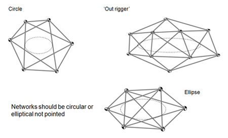
Fig 2: Good survey network shapes
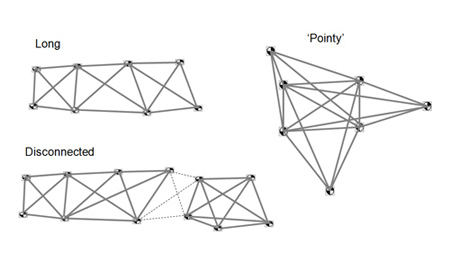
Fig 3: Poor survey network shapes
Examples of good network shapes are shown in Figure 2 where the CPs are shown as points and distance measurements between them are grey lines. For each design the main area of interest is within the dotted ellipse shape and the CPs have been arranged around the outside. Each CP has a distance measurement to a minimum of four of the other nearby CPs and the measurements form braced quads.
The Circle shape is one often used for very small sites or for small parts of a site where detailed recording is needed, perhaps for recording using planning frames or a photomosaic. None of the distance measurements cross the main part of the site so this can be used for recording tall structures where there is no clear line of sight from one side to the other. The Ellipse shape is similar and is used where you can measure across the site without snagging the tape measure. The most commonly used network shape is the Outrigger which is a series of interlinked braced quads with the addition of a couple of 'bracing' points along the outside of the long edge.
Figure 3 shows some poor network designs. These designs can be used, you may see examples of Pointy networks in older reports on shipwreck surveys, but the quality of positions for the Detail points positioned from them can be poor. The Long network suffers from a similar problem at the ends but just needs the addition of bracing points to turn it into the better Outrigger design. All parts of the CP network need to be connected together with a minimum of four measurements otherwise you get a Disconnected network; but this too is easily fixed by adding the few missing measurements.
These are idea designs and in practice the shape of the network deployed on the site is a compromise. It may not be possible to place the CPs exactly where you want them because of the shape of the seabed or parts of the structure may be in the way so you can't run a tape between two points without moving one a little. But so long as the CPs surround the whole site and the network shape remains rounded and not pointy the survey will still work well.
Sites can grow in size as more of it is discovered and the CP network needs to grow with it. If the site grows beyond the extents of the CP network then grow the network around the site. Avoid measuring to Detail Points outside the CP network as the quality of the positions for those points will be poor.
Secondary Control Points
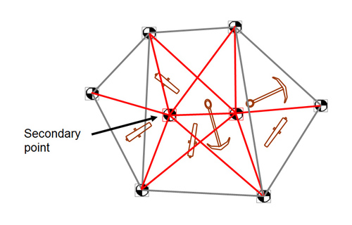
Fig 4: Secondary Control Points
Most sites are wider than the maximum 20m recommended distance between CPs and many are tall so you cannot measure directly from one side to the other. The solution to both problems is to use Secondary Control Points (Fig. 4).
The points placed around the outside of the site are the Primary CPs, these should remain in place for the life of the project and should not move if the site changes, or parts of it collapse. But we can place other control points inside the ring of primary CPs which are then called Secondary CPs. The Secondary points are still survey control points that can be used to position Detail points but they are ones that are allowed to be moved by an excavation or may be placed on structure that may move over time. The Secondary CPs are all positioned relative to the Primary points, so if they are moved they can simply be reinstalled close by the original location.
Height and Depth
It cannot be stressed enough how important depth or height measurements are to a 3D survey. Although a site may look flat it is likely that depth differences across the site are larger than the position accuracy that is required, so if heights are ignored the survey will not be accurate. Also, if the site is not flat and no depth measurements are added then it will be very difficult for the software to calculate the positions of the points.
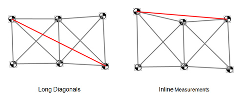
Fig 5: Long diagonal and Inline measurements
What can help with ensuring that the survey produces a good result is to place control points at different heights across the site if possible.
Measurements to Avoid
It may appear to be helpful to measure the diagonal distance across two braced quads as shown in Fig 5 (left), but long diagonal measurements are not often helpful. They can be useful for helping position points at the ends of a network if the distances are less than 20m. More often these diagonal measurements are longer than the maximum recommended 20m length and they can also cause problems in processing.
The other measurement to avoid is one that goes between the outer two points in a line of three points as shown in Fig 5 (right). These inline measurements do not help with positioning and can cause problems in processing so should not be used.
Typical Networks - Low-lying or Flat Sites
Using the rules above we can create typical network shapes for two kinds of site; sites that are flat that you can measure across and sites that are not flat where you cannot measure directly from one side to another.
Where you can measure directly across the site the network is simpler and includes fewer CPs. In the example in Figure 5 below the shipwreck is low lying on the seabed, approximately 40m long and 15m wide. Eight primary CPs surround the wreck with four secondary CPs installed on the keel running through the middle of the site. The measurements between sets of four CPs form braced quad shapes. The network includes 12 points and positioned with 31 distance measurements plus 12 depth measurements.
In Figure 6 the finished CP network is used to position 26 detail points with four distance measurements and a depth for each detail point.
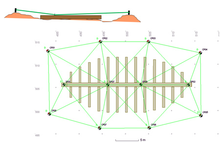
Fig 5: Control point network for flat sites
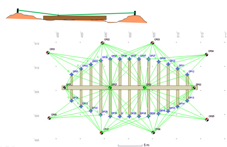
Fig 6: Detail points on a flat site
Typical Networks - Sites That Are Not Flat
Control point network shapes need to be a little more complicated where there is no clear line of sight from the CPs on one side of the site to those on the other side. The CP network has to be designed to take the measurements up and over any structure that is in the way and this is done using Secondary CPs. In Figure 7 the cross section of the site in the top left corner shows the problem, the structure is tall so it is not possible to directly measure from a CP on one side of the site to a CP on the other. Secondary CPs have been placed on top of the site so the measurements effectively go up and over the top of the site. The same outer ring of eight primary CPs and line of four secondary CPs on the keel used in the previous example have been joined by four secondary points placed on the edge of the site. The set of 16 points is tied together with distance measurements forming braced quad shapes, plus a depth measurement for each point.
In Figure 8 the finished CP network is used to position the same 26 detail points with four distance measurements and a depth for each detail point.
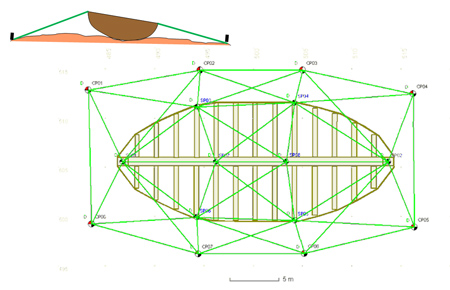
Fig 7: Control point network and measurements on a tall site
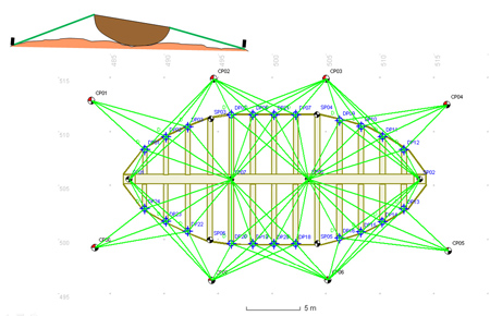
Fig 8: Detail points and measurements on a tall site
Other Recommendations
- Place the points in obvious locations so they are easily found
- Make sure each CP is clearly labelled
- Locate points clear of kelp and weed to avoid snagging the tape measures
- Treat groups of artefacts and structure more than 30m apart as separate sites, tie the positions together with GPS position fixes on the surface