Techniques > Surveying > Survey Methods > Offsets, Ties and Radial Methods
Techniques: Offsets, Ties and Radial Survey Methods
Version date: 16 October 2016
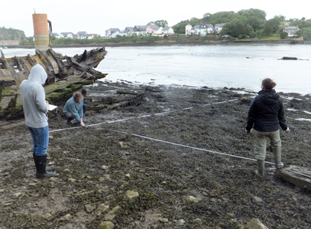
Fig 1: Offset measurement from a baseline with one tape measure
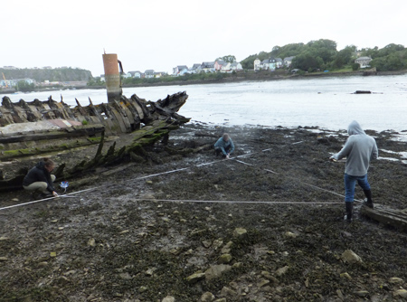
Fig 2: Ties measurement from a baseline with two tape measures
Offsets and ties are simple survey techniques that require
two people to make the measurements. The first step for both methods is to set out a tape measure
through the centre of the area to be recorded, this is called a
baseline
 Tape Baseline
A tape measure laid between two Control Points
. Distances are measured from this baseline to features on the site using another tape
measure or a measuring rod.
To position using an offset a single measurement is made from the feature to the baseline, meeting where the offset measurement is at right angles to the baseline. To position using ties, two or more measurements are made from the feature to two or more separate points on the baseline. Offsets and ties can be used for assessment surveys over large areas or for picking up detail in recording surveys.
Over short distances of a few metres both offset and ties measurements can position points to an accuracy of 30mm. Over longer distances the position accuracy of offsets is limited as it is difficult to estimate the right angle to be measured at the baseline and setting it out correctly would be very time consuming. A problem that affects both offsets and ties is that long tape baselines can move sideways and do not provide a fixed reference for the offset or tie measurements, especially in a current or swell underwater. If improved accuracy is required then an alternative technique should be used such as 3D trilateration. Because of the problems in measuring a right angle for an offset, ties should be used where the feature is further than 3m from the baseline or a more accurate position is required. Additional tie measurements made to each feature can be used as checks on other ties or offsets. If more than one point on an object is positioned then it can be oriented on the plan, if the length of the object is also measured then this can be used as a check measurement.
The offsets and ties techniques are recommended for use in confined areas such as in rock gullies or within ship structure.
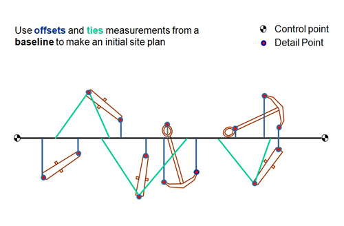
Fig. 3: Offsets and Ties measurements on the same baseline
Offset Method
- Set up two control points on site, through the middle of the area to be recorded ensuring a clear line of sight between them.
- Lay a tape measure between the two points, ensure that the tape is at the correct tension.
- Ensure each point is securely fixed, as it will be pulled on by the tape measure.
- One diver visits each feature and holds the free end of the tape measure. The other diver records the distance from the feature to the baseline and the distance along the baseline, where the tape crosses the baseline at right angles.
- Record the depth of each feature and seabed type at the same time.
- The right angle point can be found by swinging the tape measure and finding where the distance is the shortest
- Note which side of the baseline the feature is located
- The distance from the control point should be limited to 10m for assessment surveys, with this method position accuracy reduces with distance so keep the measurements short.
- In poor visibility it may be useful to have a second diver swim up and down the tape to ensure that it is not snagged.
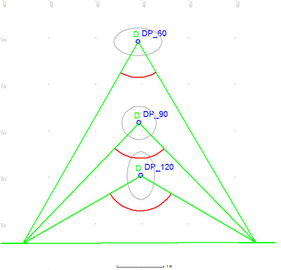
Fig. 4: Distance measurement angle should be between 60° (upper point) and 120° (lower point)
Ties Method
- Set up two control points on site, through the middle of the area to be recorded ensuring a clear line of sight between them.
- Lay a tape measure between the two points, ensure that the tape is at the correct tension.
- Ensure each point is securely fixed, as it will be pulled on by the tape measure.
- One diver visits each feature and holds the free end of the tape measure. The other diver records the distance from the feature to two points on the baseline.
- Note which side of the baseline the feature is located, left or right. The left side of the baseline is on the left when looking down the tape measure from the zero end.
Other points to remember:
- The distance between the points on the baseline should be roughly the same as the distance between the feature and the baseline
- At the feature the tapes should meet at an angle of between 60° and 120°, as shown in Fig. 4 right
- Record the depth of each feature and seabed type at the same time
- The distance from the control point should be limited to 30m for assessment surveys
- In poor visibility it may be useful to have a second diver swim up and down the tapes to ensure that they are not snagged
Radial Method
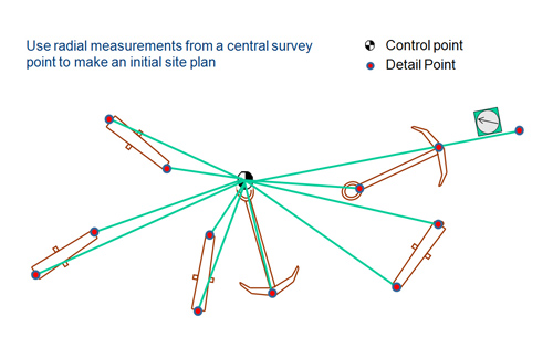
Fig. 4: Distance measurement angle should be between 60° (upper point) and 120° (lower point)
The simplest form of radial survey only requires a single diver with a tape measure and compass. One end of the tape is attached to a point in the middle of the site. The diver simply swims around the site recording the distance and bearing of each feature from the central point.The positions of the points are assumed to be on the same level as the control point so this is provides positions in two-dimensions. It would be possible to correct for the depth of each point but this technique is not accurate enough to warrant it, depth information in the form of spot depths of features can be recorded at the same time. Radial survey techniques are most easily used on flat sites with little kelp cover, places where the tape measure is not likely to be snagged. This technique is simple enough for deep sites and for sites with very poor visibility this technique can be easier to use than simple sketching.
The main practical limitation of this technique is the length of tape measure that can be used on the site. The main survey limitation is the ability to measure the bearing accurately, in this technique position accuracy decreases as distance from the control point increases.
- Install a single fixed control point in the centre of the site as high as possible.
- Ensure the point is securely fixed, as it will be pulled on by the tape measure.
- Visit each feature and record the distance with the tape measure and bearing with the compass back to the control point.
- Record the depth of each feature and seabed type at the same time.
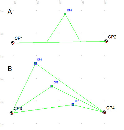
Fig. 5: Ties method (A) should be used and other method (B) should not be used
Methods to Avoid
Figure 5 shows two similar ways to position detail points using two Control points. The method (A) shown at the top is the correct one to use. In the method (B) at the bottom the measurements to three Detail points are made directly to the two control points rather than to the baseline between them.
Although method B looks simple and easy to do it should not be used. The position accuracy of points very close to the line between Control points CP3 and CP4 is poor as it is for points a long way away from that line. This is because of the angle the two distance measurements meet at each Detail point; the measurements should meet at an angle of between 60° and 120° and if they are much larger or smaller than this then the position accuracy will be poor.
Method B is sometimes known as 2D Trilateration.
