
Techniques > Surveying > Survey Methods > Making Photomosaics Underwater
Techniques: Making Underwater Photomosaics
Version date: 12 August 2018
Introduction
A photomosaic is a single photographic image created by combining a number of smaller, overlapping images. Photomosaic images are sometimes created as a plan view of a shipwreck site or as a record of the elevation view of a shipwreck on the foreshore. A mosaic image may be more easily interpreted than a drawn site plan or may be more easily understood by the public. Associated with plan and elevation mosaics are a special kind called panoramas, these are sequences of images taken at different angles around a single point.
Simple in principle, accurate mosaics are hard to create in all but the best conditions for the many reasons explained below. The images for a mosaic are often quick to collect but time consuming to process but they can provide a very high level of recorded detail difficult to equal using hand drawing methods. They work well underwater where the visibility is good and the camera can be placed high above the wreck, but in low visibility or on weed-covered sites the results are often disappointing and a planning frame survey would be better. Distortions in the images and problems of alignment can sometimes produce mosaics that look good but are not a valid representation of the site so some form of survey quality control is essential.
Mosaics have been used for recording shipwreck sites in deep water where time on site is very limited as most of the work in creating the mosaic happens afterwards in post-processing. In recent years the photomosaic has been superceded by 3D photogrammetry as the data collection method is similar but the newer method can produce a detailed and accurate 3D model of a site, rather than just a flat picture.
Click on any image below to show a larger version.
Method
A mosaic is created by joining together a number of overlapping images and converting them into a single, seamless picture. Including a photographic scale in the mosaic then allows you to take measurements from it or to convert the photograph into a scale drawing. A number of software programs can be used to create photomosaics but one of the most commonly used is Adobe Photoshop. Starting with a picture in the middle of the set of images, one image adjoining it is aligned using features shown in both photographs. This process is repeated with the other images until all are joined together.
When using a zoom lens on the camera ensure that you keep the zoom the same for each photograph as this will make it easier to merge the photographs. If you want to include higher resolution images for parts of the mosaic then move the camera rather than zooming in, see High/Low Altitude mosaics below.
Fig 1: Separate images (A) are merged together into a single, seamless image (B)
Figure 1 above shows three photographs (A) being merged together (B), the transparency of the middle photograph has been reduced so you can see how the images overlap. Note that the image on the left has had to be rotated slightly so that it lines up with the middle image.
Figure 2 below shows the final image created by merging 14 separate images of the wreck of the Severn Collier on the foreshore, see the example Severn Collier Hull Photomosaic. A scale has been included in the picture so the dimensions of the timbers and fixings can be measured from the photograph.
Fig 2: A photomosaic of the starboard side hull of the Severn Collier at Purton
In contrast, Figure 3 below shows the bow of the early Royal Navy submarine A7, partly buried in a muddy seabed in 40m water depth. The overlap of the images has been highlighted by making them partly transparent so you can see how the mosaic was put together. This mosaic was made from 13 separate images and is at the stage where the images are being aligned, the next step is to blend them together into a seamless picture. The photographs were taken in low, natural light and low visibility which is why they are dark and the contrast is poor.
Fig 3: Mosaic of the bow of the A7 submarine, shown under construction to highlight the image strips and the overlap between them
Problems
Tilt Correction
Fig 6: The effects of camera tilt in two axes
It is important to ensure that the camera is pointing in the same direction for each photograph in the mosaic. When making a mosaic of a shipwreck from above the camera must be pointing straight downwards as any tilt will distort the image as shown in figure 6. The tilt can be in two axes; tilting the camera forwards or backwards from vertical adds pitch error while tilting the camera to one side adds roll error while tilts in both axes at the same time can produce complicated distortions.
Although it is possible to correct for small distortions in software it is far better to avoid tilting the camera when taking the photographs as correction can be difficult when the camera a is tilted in both the pitch and the roll axis. Fitting a small bubble level to the back of a camera housing helps guide the photographer to keep the camera level when taking photographs straight downwards. Bubble levels can also be fitted into the flash gun hot shoe on the top of many cameras which can be used to level the camera when taking vertical photographs of structures on land.
Alignment Errors
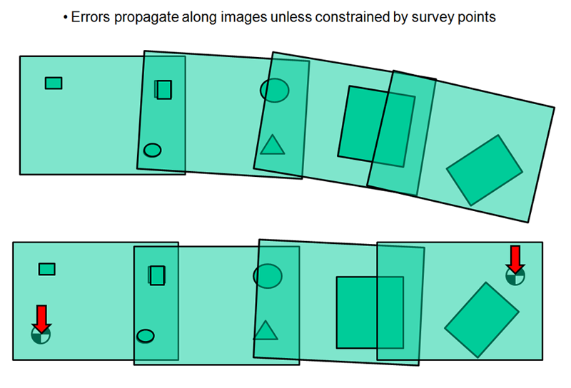
Fig 7: The effects of alignment errors
With the photographs corrected for distortion and tilt they are now ready to be joined together.
Starting with a picture in the middle of the set of images, one image adjoining it is aligned using features shown in both photographs. Any mistakes in aligning each pair of images will then affect the subsequent ones, so the error will 'propagate' down the strip of images causing it to bend (Fig. 7A). This is a very common problem when creating a photomosaic.
Angular errors are introduced when two images are not quite lined up at the same angle, offset errors shift two pictures slightly and scale errors are introduced when one picture is slightly closer than the other. Angular errors are the most common and these create a bend in the mosaic. The effect is usually noticed when trying to align two strips of photographs into a wide mosaic as often the sides of the two strips do not line up properly.
On land this is less of a problem as straight edges of structures and features makes lining up pictures relatively simple, as in Fig. 2 above. Underwater the problem is more common as poor visibility, low contrast pictures and the eroded edges of structures make aligning images more difficult. Some solutions that have been used include
- Laying a straight tape measure through the area to be photographed as this acts as a reference when aligning the images.
- Placing highly visible markers throughout the site that show up very well in the photographs and can be used to help align images, yellow Disk-mark tags work well for this.
- Make survey control points more visible and then use the points to help align the photographs (Fig. 7B). Scan or exported the site plan to an image file (TIFF or PNG) then use it as a framework on which to align the individual pictures that form the mosaic.
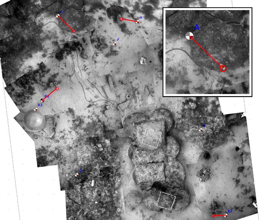
Fig 8: Distortion in a photomosaic, red lines show differences in position between the site plan and the mosaic
An example of the effect of distortion can be seen in figure 8. At first glance the mosaic looks like it is a good representation of the shipwreck site. The mosaic shows the ship's cargo in the centre, pale areas of sand and dark reef as well as some of the artefacts on the site. This site was also surveyed using 3D trilateration so the positions of the survey control points were known to a few centimetres over the whole site. When the mosaic added to the site plan and the positions of the survey control points were compared, large distortions could be seen in the mosaic. Survey control point A shown in the box on the image was located on the mosaic 1.5m away from the known survey control point location. As survey point A was just 6.5m from the centre this showed that the mosaic had a very large scale distortion.
Some very high quality mosaics have been created of shipwreck sites in deep water using remotely operated vehicles (ROVs) or autonomous underwater vehicles (AUVs). These vehicles provide an ideal platform for mounting downwards-pointing cameras; the vehicles are stable, their subsea positioning systems can provide centimetric positioning accuracy even across sites hundreds of metres wide, they can follow a predetermined track across a site with the ideal amount of image overlap, they can maintain a constant height above the seabed and they can provide lots of artificial light to add contrast and colour to the pictures. The images taken underwater can also be tagged with the vehicles position and attitude so creation of the mosaic is greatly simplified.
Creating Photomosaics Underwater
Working underwater brings additional problems when creating photomosaics. Where the visibility is good and there is plenty of ambient light creating a mosaic underwater is straightforward but unfortunately many sites lie in water with poor visibility. If the visibility is poor the details in the photographs will be blurred and it limits how far away the photographs can be taken. Lower light levels reduce the contrast in the images making it difficult to differentiate wreck from seabed, adding artificial light may introduce backscatter in the pictures again reducing visibility, or may obscure features with shadows from the lights. Even weed in the water between the camera and the seabed can obscure important details.
Marine growth on the wreck will hide details when photographed so this method does not work well on weed covered sites. Removing the weed is time consuming and can possibly damage the site if not done carefully. It may be better to draw the site using planning frames where the diver can move the weed and touch the structure to find the edges to draw.
But it is in lower visibility conditions where we most need a photomosaic. In poor visibility it may not be possible to see the whole site from one place so getting an idea of the layout of a shipwreck can be difficult. Creating a photomosaic of the site would allow it to be seen as a whole, something that could not be done underwater.
Some impressive mosaics of shipwreck sites have been created where the conditions were good, such as the 37.5m (123ft) long Rouse Simmons wreck which lies in 52m (170ft) depth in Lake Michigan (Fig. 9). This site was recorded with a video camera pointing downwards and mounted on the front of a diver propulsion vehicle. From the video 242 overlapping digital still images were captured and were converted into a photomosaic. Click on the image to show a larger version.
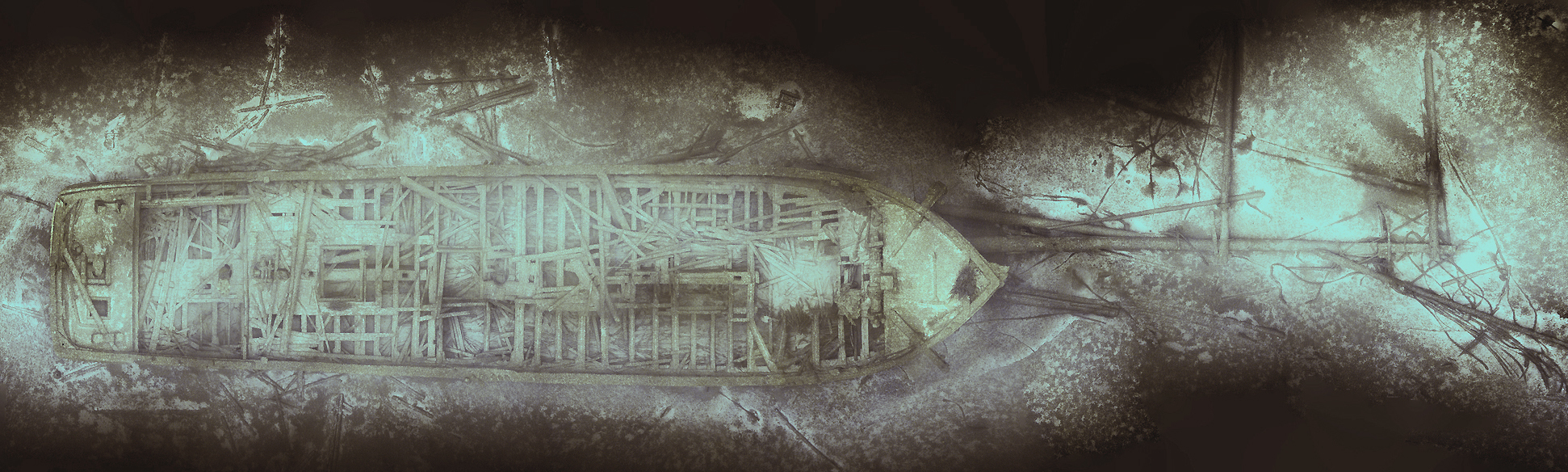
Fig 9: The 60m long photomosaic of the schooner Rouse Simmons created by the Wisconsin Historical Society
When the visibility is not good then it is better to reduce the distance between the camera and the object being photographed so there is less water in the way to blur the images. Being closer to the object then less of the object can be seen. If the focal length of the camera lens is kept the same, to cover the same area you would need to take more photographs, which in turn would take longer to process into a mosaic and would introduce more errors. Figure 10 was made up from photographs just a few metres above the deck of the armed trawler Elk using a camera with a 11mm rectilinear lens. Note that fisheye lenses cannot be used for making mosaics. See the example Mapping the Armed Trawler Elk.
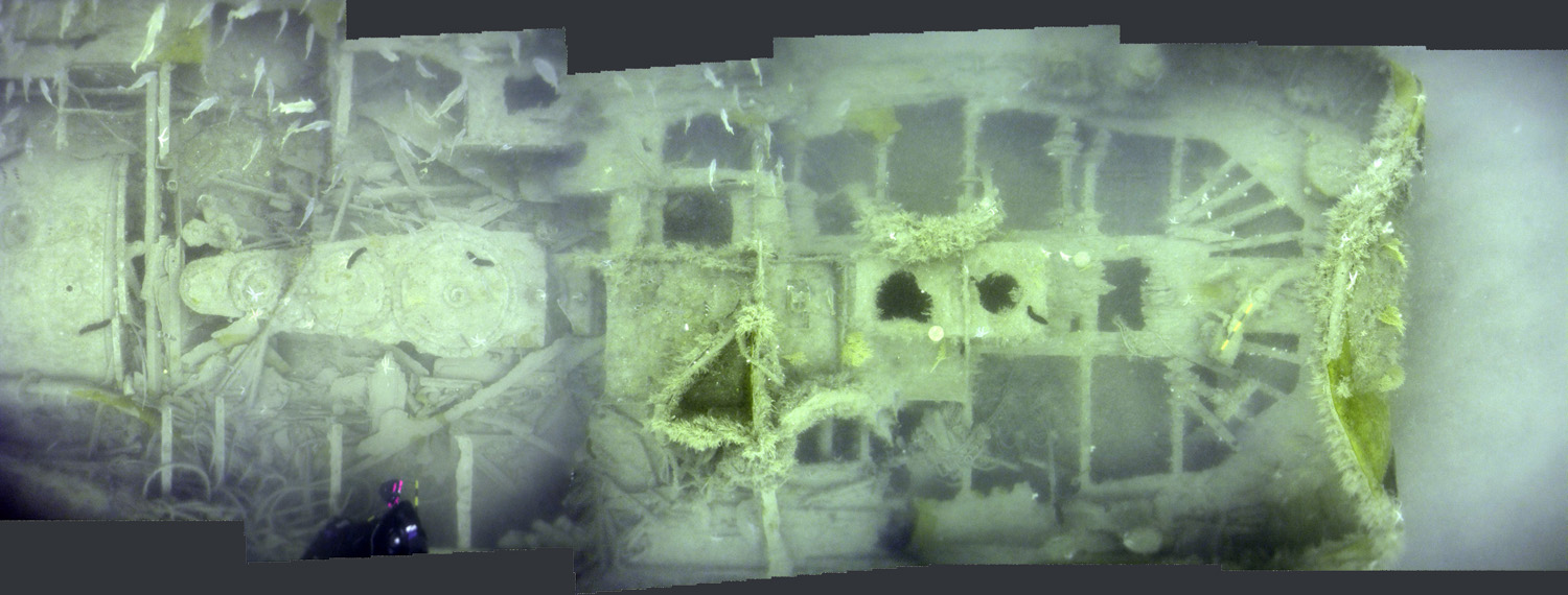
Fig 10: A mosaic of the plan view of the stern of the armed trawler HMT Elk created by the SHIPS Project
Lens High/Low Altitude Mosaics
In low visibility the images get less well defined the further away the camera is from the subject. Photographs taken close to the subject show more detail and are less affected by blurring but can often be more difficult to position correctly on the site. Some of these problems can be overcome by combining high altitude and low altitude images as shown in figure 13. Figure 14 is an example of this in practice. The larger background image was taken from further away so the detail is lost but the outline of the timbers on the seabed scan still be seen. Two images of the timbers taken much closer to the seabed were then superimposed on to the background image providing a detailed image of the timber. So the background image is used to define where the objects are in relation to one another and the closer images provide the detailed information. Click on figure 14 to see a larger version.
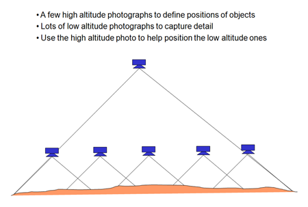
Fig 13: Merging high level and low level photographs in low visibility
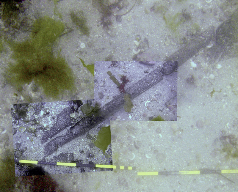
Fig 14: Composite image with photographs taken at different altitudes
Procedure
The procedure for making a photomosaic:
- Measure the distortion in the camera by photographing photographic scales or a planning frame
- Take the photos with 30%-50% overlap
- Correct the images for distortion
- Correct the image colour
- Correct the images for tilt errors
- Align images using control points or a baseline where possible
- Smooth the edges of the images then create a single image
Equipment List
- Camera - Used for taking photographs on land or underwater. Better quality cameras make better quality photomosaics.
- Photo Scale - Always include a photographic scale in the mosaic
- Planning frame - A planning frame can be used to help correct distortions in the photographs
Related Pages
- Problems with Photography Underwater
- Example - Severn Collier hull photomosaic, Purton, UK
- Example - Mapping the armed trawler Elk (1940), Plymouth, UK
- Planning or Drawing Frames
- Mosaic of the Swedish warship Mars (1564) on the Stachuraphoto web site
- The Rouse Simmons mosaic by the Wisconsin Historical Society on the Advanced Diver magazine web site
- Example - the canaller Walter B. Allen mosaic by the Wisconsin Historical Society on the Museum of Underwater Archaeology web site