
Techniques > Surveying > Survey Methods > GPS Positioning
Techniques: Positioning using GPS
Version date: 16 October 2016
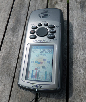
Fig 1: Garmin 76CSx hand-held GPS
Since the arrival of small and low-cost Global Positioning System (GPS) receivers it has been easy to find out where you are in the world. Fitted into hand-held instruments (Fig. 1) and mobile phones they are readily available for use in site survey work.
The GPS positioning system only works above water as the radio signals from the satellites they use do not pass through seawater. This limits their use in underwater site surveys to positioning marker buoys on the surface and for positioning shot lines for seabed searches. On land the GPS can be used for more tasks including positioning archaeological sites, stray artefacts and structure debris fields. Survey quality GPS that have centimetric accuracy can be used for detailed survey work on foreshore sites.
The GPS receives signals from a number of satellites in the sky, the instrument does not transmit any signals it simply receives what it can. Modern GPS receivers are quite robust and will work even where the satellite signal coverage is poor, such as under trees and around tall buildings. A minimum of four satellite signals is required for a position fix but as so many satellites are available there can be 8 or more in view at any time. Satnav or GPS is more correctly known as GNSS, or Global Navigation Satellite System which includes the US NAVSTAR, Russian GLONASS and European Galileo satellite systems.
Position Fixing on Land
Recording the position, or taking a 'fix', for a point on land is straightforward:
- Switch on the GPS receiver
- Leave the GPS to work out its position
- Press the 'Fix' or 'Mark' button to record the current position
With position accuracies of approximately 2m a typical hand-held GPS receiver can usefully be used to position objects more than 10m apart.
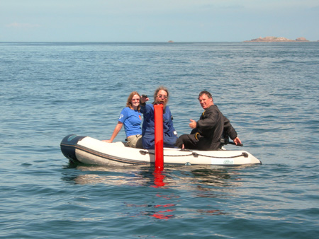
Fig 2: Taking a GPS position fix on a marker buoy
Positioning for a Circular Search
For an underwater circular search a shot line has to be dropped in the middle of the search area, see Circular Search. For this task the GPS is used to guide the boat to the point where the shot line is to be dropped. If the point is added as a Waypoint to the GPS then the GPS itself can guide the boat driver to the correct place. Ensure that the vessel is travelling slowly and in a straight line up to the waypoint location as tight turns or big speed changes can cause the GPS to report positions that are many metres away from where the boat really is.
Positioning a Marker Buoy
The GPS can be used to position a point on the seabed, perhaps for positioning an object located during a search. The GPS is used to position a marker buoy on the surface tied to light line held by a diver on the seabed, with the diver ensuring that the buoy is held directly over the point to be positioned. The boat with the GPS receiver should approach the buoy carefully from downwind, making sure that the boat does not run over the buoy and catch the line in its propeller (Fig. 2). Whilst alongside the buoy on the downwnd side a series of three position fixes are taken with the GPS. The downwind side is chosen so the boat is blown away from the buoy and not over it. Three position fixes are taken so an average can be calculated which will improve the accuracy of the fix.
Positioning a Site
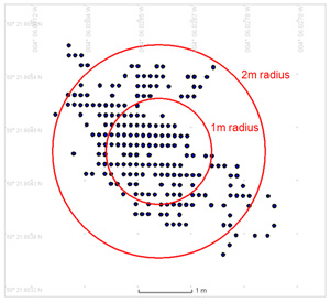
Fig 3: Static fix test for a Garmin GPS
A GPS can be used to position two ends of a shipwreck site to calculate its position and orientation. This method can be used on sites on land or underwater. For sites larger than 20m long the GPS can simply be used to take a position fix of two known points on the site more than 20m apart, two survey control points are ideal for this.
For sites smaller than 20m in length run a tape measure through the site, the tape should be at least 20m long, laid straight and tight. Take position fixes at the two ends of the tape, with at least three position fixes at each end, note the distance along the tape that the measurements were taken and note where on the site the tape baseline passed through it. The position fixes define the location of the tape baseline and your additional measurements define where the site is relative to the tape. This can be calculated by hand but this can also be calculated for you by putting the points and measurements into Site Recorder.
The 20m baseline is used to obtain a high quality heading for the site, a shorter baseline of as small as 10m could be used but this would make the calculated heading much less accurate.
Position Accuracy
The accuracy of hand held GPS receivers has improved greatly in recent years so standalone they can provide a useful accuracy of under 10m. Differential corrections can be used to improve the quality of the position but this requires a local differential reference station to be set up if a wide area system is not available. Free wide area correction services are only available in specific areas such as WAAS in the US and EGNOS in Europe. Paid-for services such as Fugro Marinestar can provide worldwide coverage with high accuracy but are expensive.
A static fix test can be used to determine the accuracy (precision) of a GPS receiver. The receiver needs to be one that can record its own positions or can send its position to a computer over a serial link. Place the GPS receiver outside where it has a clear view of the sky, log or record the positions calculated by the GPS and plot the result. Figure 3 shows the results for a static fix test of a Garmin hand held GPS with EGNOS corrections enabled, the majority of the position fixes are within a 1m radius, some within a 2m radius and all within 2.5m.
Equipment List
- Shot line - Use a 15-20 kg weight, a large fender as a float and rope at least 10 mm diameter
- Hand held GPS - To take a position fix of the shot line buoy and delayed marker buoy on the surface.
- Delayed SMB - A delayed marker buoy for indicating when the object has been found