Techniques > Research > Planning Frame Drawings
Research - The Accuracy of Planning Frame Drawings
Version date: 16 October 2016
Aims and Objectives
Question: How accurate are planning frame drawings and what can we do to improve their quality?
The aim of this test was to make empirical measurements to demonstrate the accuracy of planning frame drawings. A representative timber test piece was constructed that could be recorded in the same way by a number of different people and the results compared with a known standard. Different methods of recording were also tried using a planning frame and a sheet of clear plastic.
- Construct a 1m x 1m timber test piece to represent ship hull structure to be recorded
- Get a number of people to draw the same test piece with a planning frame and compare the results
- Record the test piece by hand using a clear plastic sheet
- Compare the results between planning frame and plastic sheet
Equipment
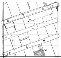
A 1m x 1m drawing frame test piece was made from scrap timber to represent the outer planks and three frames of a small boat (Fig. 1). The ‘planks’ were screwed to the ‘frames’ from the underside so the modern fixings could not be seen on the side to be recorded. Interesting features were added to the piece; the end of one plank was omitted, some planks show signs of damage, one plank has a waney edge while details such as carpenters marks, trenails, nail holes and coach bolts were included.
The test piece was made flat with raised frames as this would remove any problems with recording a curved three-dimensional structure using a two-dimensional recording method. The frames were deliberately not aligned with the sides of the drawing frame to make the drawing more difficult as the lines on the frame would not align with the planks. The test piece also had two yellow survey detail points added so the test piece could be used during survey training exercises.
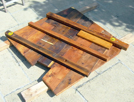
Fig 1: The 1m square planning frame test piece built from timber with two yellow survey detail points added
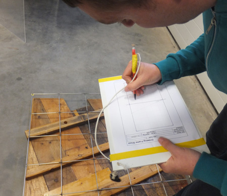
Fig 2: Using the 1m x 1m stainless steel planning frame to record the test piece onto a 1:10 form
Method
Once constructed, the first step in recording the test piece was to create a baseline standard image of the test piece that was as precise a representation that could be achieved to the tolerance required. To do this the test piece was photographed in a way that minimised distortions, the 'frames' stand proud of the planks so the piece was photographed at a distance using a low distortion zoom lens to minimise light ray divergence. The photograph was taken from directly above with the camera centred on the middle of the piece and using a flash to ensure even lighting.
For each test subject the test piece was drawn at a scale of 1:10 scale using the same stainless steel mesh drawing frame (1m x 1m with 200mm squares) (Fig. 2) laid directly on top to minimise parallax errors. The drawing was scanned and converted to a TIFF image (Fig. 4).
The reference image (Fig. 3) and scanned drawing were imported into Site Recorder as Drawing Frame objects. The reference image was correctly sized using a scale in the photograph and the scanned drawing was scaled using a measured distance between two known points.
Both images were digitised using the drawing tools available in the program (Figs. 4, 5, 6), this reduced complex photographs to simple line drawings that were much easier to compare.
Results
Planning Frame Drawing
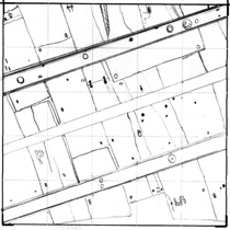
Figure 3 is the reference photograph and Figure 4 shows the digitised and colour rendered reference image traced from it.
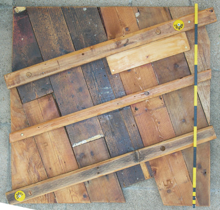
Fig 3: Standard photograph of the test piece
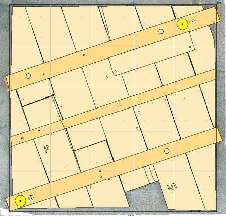
Fig 4: Reference image traced from the photograph
Two planning frame drawings are shown below, each were scanned and digitised in Site Recorder then overlaid on top of the reference image so the drawing (blue lines) could easily be compared with the reference (black lines).
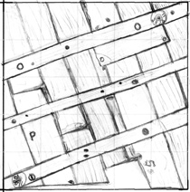
- Drawing 1 (Fig. 5) was drawn by someone with experience in the use of planning frames, took 25 minutes to complete and records all features bigger than 5mm
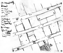
- Drawing 2 (Fig. 6) was drawn by a user who had never used a planning frame previously taking a similar time to complete
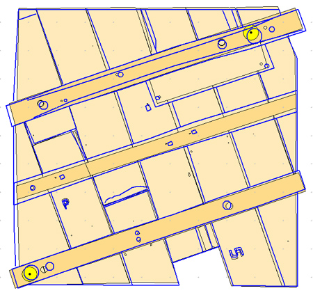
Fig 5: Drawing 1 - Digitised drawing from an experienced user
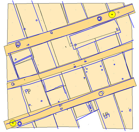
Fig 6: Drawing 2 - Digitised drawing from an inexperienced user
Drawing 1 was done by an experienced user. The majority of the features are recorded correctly apart from the middle 'frame' which is too wide and the rectangular 'patch' which is too large in size. Pencil line thickness is approximately 6mm at this scale and errors in the drawn lines are in the order of 12-15mm. Drawing 2 was done by an inexperienced subject but the representation is surprisingly good. The largest positioning error is on one of the plank edges which is in error by 35mm.
Repeat Drawings
Repeating the test with different people doing the recording showed a large variation in the level of detail recorded and how the features were represented.
The variation in the drawings suggests that an agreed way of representing features is required for any project to ensure that the same features are recorded in the same way.
Plastic Sheet
Next the timbers were recorded at 1:1 scale using a clear sheet of Perspex 1m by 1m in size and 6mm thick by the same inexperienced user that created Drawing 2. The Perspex was laid onto the timbers and their outline was drawn directly onto the plastic using a chinagraph pencil and a plastic rule (Fig. 11). A black pencil was used for the test but this was hard to see against the dark wood and yellow pencil has since been found to be more visible. The plastic sheet is heavy and would be hard to handle underwater in any surge or current. The plastic sheet tends to slide easily so it was necessary to start by recording a number of clearly identifiable features on to the sheet that could be used to re-align the sheet after it moved. When the drawing was complete the plastic sheet was laid on the ground on to a pale coloured backcloth and it was photographed from directly above. The photograph was again imported into Site Recorder and the features digitised.
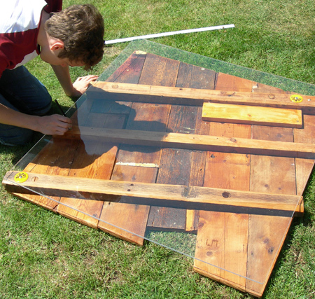
Fig 11: Drawing using the plastic sheet
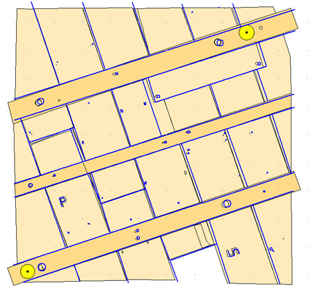
Fig 12: Drawing 7 - Digitised plastic sheet drawing over the test image
Drawing 7 (Fig. 12) is the digitised 1:1 line drawing by the inexperienced user shown over the colour rendered reference drawing. Here we can see a much high degree of correlation between the two drawings than was seen with the planning frame Drawing 2 (Fig. 6). In fact the plastic sheet drawing by the inexperienced user is a better representation of the test piece than the planning frame drawing done by the experienced user.
Drawing directly over the test piece using the plastic sheet is easier than drawing to scale as you are simply tracing the edges that you can see. Also, any wobbles in the lines are far less pronounced at the 1:1 scale than they are at 1:10 so the overall quality of the drawing is better too. The drawback to the plastic sheet method is the logistics of getting the sheets on site and in position, retrieving them, copying then cleaning before they are used again. Suitable clear acrylic sheet can be expensive and how long they last in use in the field is unknown.
As well as being more precise in inexperienced hands this method has another benefit when working in poor visibility. With underwater visibility of less than a metre it can be difficult to use a planning frame because you cannot get your eyes far enough above the frame and still see the features to be drawn. With the plastic sheet the drawing is made directly on to the sheet so the user can be much closer to it when tracing lines.
Discussion
- The drawing by an experienced user (Drawing 1) produced a good representation of the test piece
- In Drawing 1 the feature positions were in error to a maximum of 12-15mm
- This drawing took 25 minutes on land and would take longer if done underwater but recorded everything bigger than 5mm
- Specifying a larger level of detail would reduce the recording time
- Drawing 2 by the inexperienced user was still useable and managed to capture the features on the test piece
- In Drawing 2 the feature positions were in error to a maximum of 35mm.
- Agreed standards are needed for how features are represented on a planning frame drawing
- The plastic sheet produces a better result than a drawing frame
Conclusions
- A working estimate of the accuracy of a planning frame drawing is 15 - 35mm
- Useful results can be obtained from inexperienced users with this method of recording
- Training and practice will improve the quality of the result
- An agreed way of representing features is required for any project
- The plastic sheet will produce better results than a planning frame
- The plastic sheet will work in very poor visibility where a planning frame cannot be used

