
Techniques > Surveying > Survey Methods > Sketching
Techniques: Sketching
Sketching is one of the most useful survey techniques. A good sketch often provides a large amount of information about a site in the early stages and it is better for explaining what has been found as a sketch is easier to interpret than a set of bare measurements. Once a survey has started we can use sketches to help record areas of the site or specific details about features.
Some form of sketch is essential before work can be planned on a new site as the size and shape of the site need to be known, as well as some idea of what can be found there. For assessing a site the initial sketches can be as detailed as you wish but should aim to give an overview rather than concentrating on one part in detail. It is important to establish the size and orientation of the site as a minimum, the position of any large features should be recorded as these can give a clue to the type and size of the ship or to help work out which end is the bow and which is the stern. The pattern of structure and features gives clues to how ship sank and can show if ship has been salvaged or disturbed by trawlers. Information about the seabed type and its general shape is also useful.
The sketch should show:
- Important features on the site in relation to each other
- Approximate dimensions of the site, length and width
- The orientation of the site, which way is north
- Note if the site is submerged, intertidal or above water
- Water depth at points across the site, or heights if on the foreshore
- Note if the site is intact, broken up or scattered, upright, on it side or upside-down
- Notes on any features or objects on the site
- Notes on potential for buried objects
- Notes on seabed types
- Potential hazards such as trawl nets
- The 'metadata' that tells us about the sketch; who drew it, the name of the site, when it was drawn, the depth, visibility and current on the site at the time
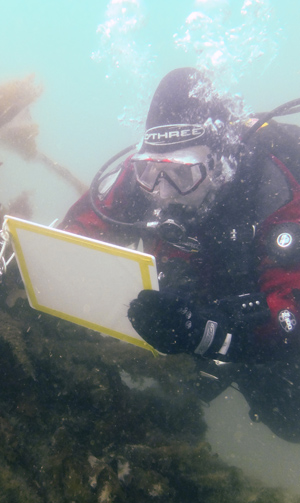
Few tools are required to make a sketch underwater; a drawing slate, pencil and waterproof drawing film with a tape measure to use as a baseline or to add measurements. Gloves may be worn in cold water but these will make sketching much more difficult, if the water is not too cold then cutting off the tips of the glove fingers on your drawing hand makes sketching easier.
Some suggestions about drawing sketches:
- Although a sketch can be drawn after a dive it is usually better to start sketching underwater as you are less likely to forget details
- For larger sites or ones where visibility is poor a tape or distance line can be laid through the site and used as a guide
- If the visibility is really bad then it may be easier to do a radial survey with a compass and tape measure
- A checklist of information to record on the sketch can be written on the slate before the dive
If the sketch was drawn underwater on plastic film then it can be copied using a computer scanner or by taking a photograph. If the initial sketch of a new site is to scale then it can be scanned and used as the starting point for the main site plan.
Anyone Can Sketch Underwater
Few people believe that they are good at sketching but experience with hundreds of volunteers shows that anyone can draw a sketch. Often the potential sketcher thinks that what is required is more complicated and intricate than the sketches we need, in fact what we want is more like directions to a railway station rather than like a Rembrandt painting. A artistic skill can be a limitation as there may be a tendency to record what you think is there rather than what is really there.
To help explain what is required a number of examples of real site sketches have been included below. Do not be surprised if the sketches look a little rough with smudges, wobbly lines and poor handwriting. Sketches like that are what most often are produced when drawing underwater, especially if gloves are worn, there is a current, the site is deep or dark. Yes, there are a few people who can produce fabulous drawings to scale in a matter of moments, but few of us are like that. The example sketches below were produced by ordinary volunteer divers.
Two things have been found to help improve skill in sketching; the first is lots of practice and the second is some basic training in engineering drawing.
Examples
Below are a number of real examples of sketches. For many the information about who did it and when has been removed.
Please click on a sketch to show a larger version.
1. Simple location sketch This sketch was attached to a dive log and was included to show the location of a cannon so it could be more easily located later on. The cannon was found in amongst a very thick bed of kelp (tall seaweed) on rocky ground that was crossed by deep gullies so initially was very hard to find. The sketch shows the main feature, a cannon, in the middle along with lines used to represent the edges of the gullys and kelp around it. The depths recorded at the time are shown as these can be useful for identifying the general area when relocating the cannon. This quick and simple sketch took minutes to do but does a good job of recording the location of the cannon. |
.jpg) |
2. Simple Sketch Plan This is a simple sketch of the wreck of the MV Fylrix wrecked in Jennycliff Bay in Plymouth, the sketch was made by a diver who had not visited the site before. The sketch shows outlines of the main features of the wreck, the upturned bow, the stern and the debris in between. Alongside the drawing are notes on what was seen and the depths recorded at the time. Little was recorded about the seabed in the area as it is flat and featureless mud. Find out more about the Fylrix on the SHIPS Project web site |
.jpg)
|
3. Initial sketch plan This is the first sketch plan of the A7 submarine sunk in Whitsand Bay off Plymouth. The site is in 40m depth, the visibility was less than 4m and there was minimal natural light. Features on the hull of the small submarine have been marked on the plan surrounded by a basic outline of the hull. Working at depth provides only a short time to draw a sketch so very little can be achieved in one dive. Photography and video can provide more information but may be harder to interpret if the visibility is poor. When planning work in these conditions it is important to keep expectations to a minimum! Find out more about this early Royal Navy submarine on the A7 Project web site |
.jpg)
|
4. Initial site sketch plan When making an initial sketch of a wreck it is often easier to lay a tape measure across the site to use as a reference. This example is an initial sketch of the wreck of the WWI armed trawler Abelard. A tape measure laid straight across a site helps to ensure that the drawing is also straight, this can be essential for the more difficult sites where the visibility is poor, it is deep or dark. The distance marks on the tape can be used to roughly mark out where each feature is on the plan without spending time being too precise. The baseline can be drawn to scale on the plan as a straight line and the features on the wreck along the tape drawn on the plan in the right place. It was possible to lay a tape measure through the middle of this wreck as it was relatively flat after being heavily salvaged. For taller wrecks it may not be possible to lay the tape through the wreck but sometimes it can be laid alongside. This sketch also includes a north arrow to show the orientation of the site as well as notes on the seabed type. Find out more about HMT Abelard on the SHIPS Project web site |
.jpg)
|
5. Sketched details over an engineering drawing For shipwrecks where the plans exist you can take copies of the plans underwater then mark them up with features seen on the site. This was one of the methods used for recording details within the holds of the Liberty ship S.S. James Eagan Layne. Copies of the plans for the ship were printed on to laser printer safe drawing film and attached to a drawing slate. The slate was taken on to the site and the features drawn on to the drawing film over the plan using a pencil. The positions of bulkheads and hatches were used to position and align the other features sketched over the plan, with notes added where the objects could be identified. Find out more about the James Eagan Layne on the Liberty 70 Project web site |
.jpg)
|
6. Sketch with dimensions The next stage up from a basic sketch is one where the main dimensions have been added. This sketch is of a section of iron steamship and has been redrawn on paper from the original that was drawn underwater. The drawing is not to scale but gives a useful impression of the plan view of this structure. |
.jpg)
|
7. Detailed sketch with dimensions If the sketch has enough detail then it is possible to produce an engineering drawing of the object that was recorded. This is a detailed sketch of a ship's boiler found on its own on a flat sand seabed, the drawing was done in 30 minutes by two divers in very poor visibility where no useful photographs could be taken. Four elevation sketches show the boiler from all sides and details of part of the structure have been drawn separately. Enough measurements have been included on the sketch to be able to create a representative drawing. |
.jpg)
|
Equipment List
- Drawing slate - An A4 or A5 size PVC slate, pencil and waterproof paper for making notes
- Pencils - For drawing
- Waterproof paper - For sketching on underwater or in the rain
- Compass - A divers hand bearing compass
- Flagging tape - Bright yellow flagging tape is used to mark objects that have been found